Individual Project (iP):
Team Project (tP):
Week 8 [Fri, Oct 2nd] - Topics
Detailed Table of Contents
- [W8.1] Design: Fundamentals
Abstraction
- [W8.1a] Design → Design Fundamentals → Abstraction → What :
Coupling
-
[W8.1b] Design → Design Fundamentals → Coupling → What :
-
[W8.1c] Design → Design Fundamentals → Coupling → How :
-
[W8.1d] Design → Design Fundamentals → Coupling → Types of coupling :
Cohesion
- [W8.2] Design Principles: SoC, SRP
- [W8.3] Project Mgt: Scheduling and Tracking
-
[W8.3a] Project Management → Project Planning → Milestones :
-
[W8.3b] Project Management → Project Planning → Buffers :
-
[W8.3c] Project Management → Project Planning → Issue trackers :
-
[W8.3d] Project Management → Project Planning → Work breakdown structure :
-
[W8.3e] Project Management → Project Planning → Gantt charts :
-
[W8.3f] Project Management → Project Planning → PERT charts :
-
[W8.3g] Project Management → Teamwork → Team structures
- [W8.4] Other QA Techniques
-
[W8.4a] Quality Assurance → Quality Assurance → Introduction → What :
-
[W8.4b] Quality Assurance → Quality Assurance → Introduction → Validation versus verification :
-
[W8.4c] Quality Assurance → Quality Assurance → Code Reviews → What :
-
[W8.4d] Quality Assurance → Quality Assurance → Static Analysis → What :
-
[W8.4e] Quality Assurance → Quality Assurance → Formal Verification → What :
- [W8.5] Testing: Intermediate Concepts : OPTIONAL
Guidance for the item(s) below:
As you do projects, you'll have to make design decisions e.g., decide between multiple design alternatives. Let us learn three fundamental design concepts that you can use in those decisions.
It is extremely important for you to know these three because they are like the DNA of every higher-level design concept.
Abstraction
Design → Design Fundamentals → Abstraction → What
Can explain abstraction
Abstraction is a technique for dealing with complexity. It works by establishing a level of complexity we are interested in, and suppressing the more complex details below that level.
The guiding principle of abstraction is that only details that are relevant to the current perspective or the task at hand need to be considered. As most programs are written to solve complex problems involving large amounts of intricate details, it is impossible to deal with all these details at the same time. That is where abstraction can help.
Data abstraction: abstracting away the lower level data items and thinking in terms of bigger entities
Within a certain software component, you might deal with a user data type, while ignoring the details contained in the user data item such as name, and date of birth. These details have been ‘abstracted away’ as they do not affect the task of that software component.
Control abstraction: abstracting away details of the actual control flow to focus on tasks at a higher level
print(“Hello”) is an abstraction of the actual output mechanism within the computer.
Abstraction can be applied repeatedly to obtain progressively higher levels of abstraction.
An example of different levels of data abstraction: a File is a data item that is at a higher level than an array and an array is at a higher level than a bit.
An example of different levels of control abstraction: execute(Game) is at a higher level than print(Char) which is at a higher level than an Assembly language instruction MOV.
Abstraction is a general concept that is not limited to just data or control abstractions.
Some more general examples of abstraction:
- An OOP class is an abstraction over related data and behaviors.
- An architecture is a higher-level abstraction of the design of a software.
- Models (e.g., UML models) are abstractions of some aspect of reality.
Coupling
Design → Design Fundamentals → Coupling → What
Can explain coupling
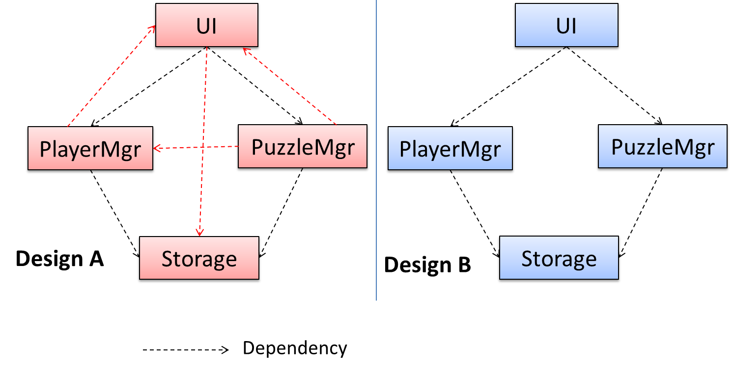
Coupling is a measure of the degree of dependence between components, classes, methods, etc. Low coupling indicates that a component is less dependent on other components. High coupling (aka tight coupling or strong coupling) is discouraged due to the following disadvantages:
- Maintenance is harder because a change in one module could cause changes in other modules coupled to it (i.e. a ripple effect).
- Integration is harder because multiple components coupled with each other have to be integrated at the same time.
- Testing and reuse of the module is harder due to its dependence on other modules.
In the example below, design A appears to have more coupling between the components than design B.
Exercises
Coupling levels of alternative designs
Discuss the coupling levels of alternative designs x and y.
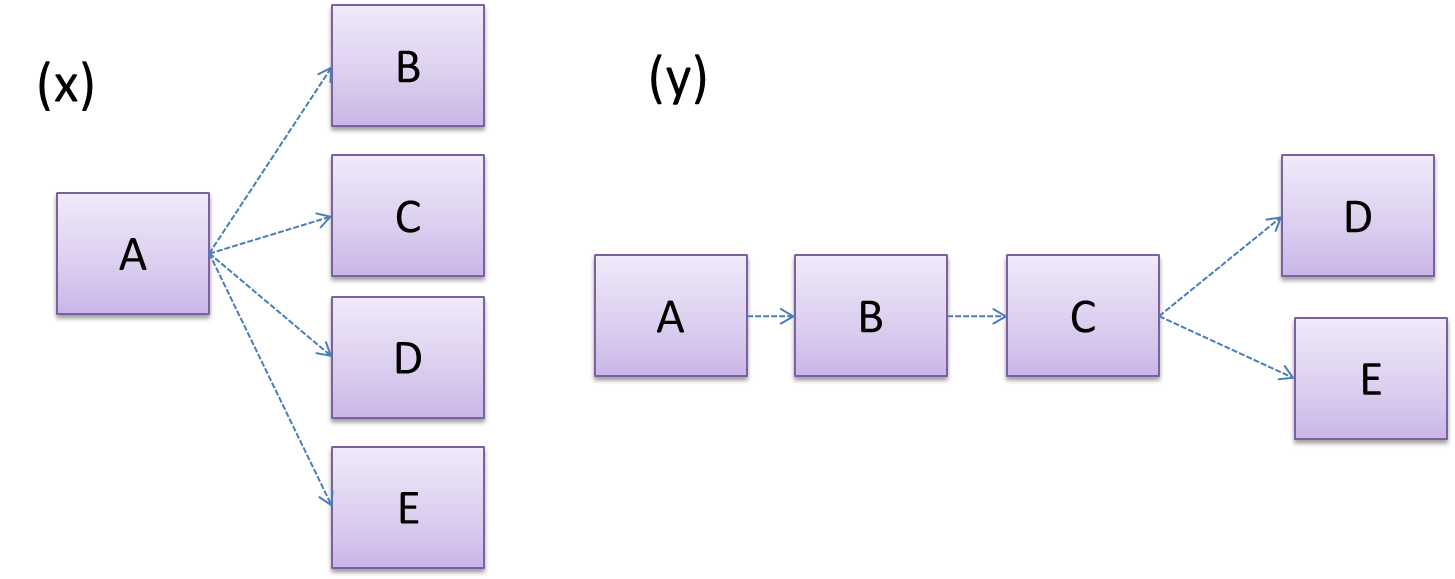
Overall coupling levels in x and y seem to be similar (neither has more dependencies than the other). (Note that the number of dependency links is not a definitive measure of the level of coupling. Some links may be stronger than the others.). However, in x, A is highly-coupled to the rest of the system while B, C, D, and E are standalone (do not depend on anything else). In y, no component is as highly-coupled as A of x. However, only D and E are standalone.
Regressions and coupling
Explain the link (if any) between regressions and coupling.
When the system is highly-coupled, the risk of regressions is higher too e.g. when component A is modified, all components ‘coupled’ to component A risk ‘unintended behavioral changes’.
Coupling and testability
Discuss the relationship between coupling and a measure of how easily a given component can be testedtestability.
Coupling decreases testability because if the Software Under TestSUT is coupled to many other components, it becomes difficult to test the SUT in isolation of its dependencies.
Statements about coupling
Choose the correct statements.
- a. As coupling increases, testability decreases.
- b. As coupling increases, the risk of regression increases.
- c. As coupling increases, the value of automated regression testing increases.
- d. As coupling increases, integration becomes easier as everything is connected together.
- e. As coupling increases, maintainability decreases.
(a)(b)(c)(d)(e)
Explanation: High coupling means either more components are required to be integrated at once in a big-bang fashion (increasing the risk of things going wrong) or more drivers and stubs are required when integrating incrementally.
Design → Design Fundamentals → Coupling → How
Design → Design Fundamentals → Coupling → What
Can reduce coupling
X is coupled to Y if a change to Y can potentially require a change in X.
If the Foo class calls the method Bar#read(), Foo is coupled to Bar because a change to Bar can potentially (but not always) require a change in the Foo class e.g. if the signature of Bar#read() is changed, Foo needs to change as well, but a change to the Bar#write() method may not require a change in the Foo class because Foo does not call Bar#write().
code for the above example
class Foo {
    ...
    new Bar().read();
    ...
}

class Bar {
    void read() {
        ...
    }

    void write() {
        ...
    }
}
Some examples of coupling: A is coupled to B if,
Ahas access to the internal structure ofB(this results in a very high level of coupling)AandBdepend on the same global variableAcallsBAreceives an object ofBas a parameter or a return valueAinherits fromBAandBare required to follow the same data format or communication protocol
Exercises
Which indicate coupling?
Which of these indicate coupling between components A and B?
- a. component A has access to the internal structure of component B.
- b. components A and B are written by the same developer.
- c. component A calls component B.
- d. component A receives an object of component B as a parameter.
- e. component A inherits from component B.
- f. components A and B have to follow the same data format or communication protocol.
(a)(b)(c)(d)(e)(f)
Explanation: Being written by the same developer does not imply coupling.
Design → Design Fundamentals → Coupling → Types of coupling
Design → Design Fundamentals → Coupling → What
Can identify types of coupling
Some examples of different coupling types:
- Content coupling: one module modifies or relies on the internal workings of another module e.g., accessing local data of another module
- Common/Global coupling: two modules share the same global data
- Control coupling: one module controlling the flow of another, by passing it information on what to do e.g., passing a flag
- Data coupling: one module sharing data with another module e.g. via passing parameters
- External coupling: two modules share an externally imposed convention e.g., data formats, communication protocols, device interfaces.
- Subclass coupling: a class inherits from another class. Note that a child class is coupled to the parent class but not the other way around.
- Temporal coupling: two actions are bundled together just because they happen to occur at the same time e.g. extracting a contiguous block of code as a method although the code block contains statements unrelated to each other
Cohesion
Design → Design Fundamentals → Cohesion → What
Can explain cohesion
Cohesion is a measure of how strongly-related and focused the various responsibilities of a component are. A highly-cohesive component keeps related functionalities together while keeping out all other unrelated things.
Higher cohesion is better. Disadvantages of low cohesion (aka weak cohesion):
- Lowers the understandability of modules as it is difficult to express module functionalities at a higher level.
- Lowers maintainability because a module can be modified due to unrelated causes (reason: the module contains code unrelated to each other) or many modules may need to be modified to achieve a small change in behavior (reason: because the code related to that change is not localized to a single module).
- Lowers reusability of modules because they do not represent logical units of functionality.
Design → Design Fundamentals → Cohesion → How
Design → Design Fundamentals → Cohesion →
What
Can increase cohesion
Cohesion can be present in many forms. Some examples:
- Code related to a single concept is kept together, e.g. the
Studentcomponent handles everything related to students. - Code that is invoked close together in time is kept together, e.g. all code related to initializing the system is kept together.
- Code that manipulates the same data structure is kept together, e.g. the
GameArchivecomponent handles everything related to the storage and retrieval of game sessions.
Suppose a Payroll application contains a class that deals with writing data to the database. If the class includes some code to show an error dialog to the user if the database is unreachable, that class is not cohesive because it seems to be interacting with the user as well as the database.
Exercises
Which class is more cohesive?
Compare the cohesion of the following two versions of the EmailMessage class. Which one is more cohesive and why?
// version-1
class EmailMessage {
    private String sendTo;
    private String subject;
    private String message;

    public EmailMessage(String sendTo, String subject, String message) {
        this.sendTo = sendTo;
        this.subject = subject;
        this.message = message;
    }

    public void sendMessage() {
        // sends message using sendTo, subject and message
    }
}

// version-2
class EmailMessage {
    private String sendTo;
    private String subject;
    private String message;
    private String username;

    public EmailMessage(String sendTo, String subject, String message) {
        this.sendTo = sendTo;
        this.subject = subject;
        this.message = message;
    }

    public void sendMessage() {
        // sends message using sendTo, subject and message
    }

    public void login(String username, String password) {
        this.username = username;
        // code to login
    }
}
Version 2 is less cohesive.
Explanation: Version 2 is handling functionality related to login, which is not directly related to the concept of ‘email message’ that the class is supposed to represent. On a related note, you can improve the cohesion of both versions by removing the sendMessage functionality. Although sending messages is related to emails, this class is supposed to represent an email message, not an email server.
Guidance for the item(s) below:
As you are still in the early stage of the project, this is a good time to learn some design principles that you can try to apply in the internal design of your product.
These principles build on top of the design fundamentals you learned earlier (i.e., abstraction, coupling, cohesion).
Principles → Separation of concerns principle
Can explain separation of concerns principle
Separation of concerns principle (SoC): To achieve better modularity, separate the code into distinct sections, such that each section addresses a separate concern. -- Proposed by Edsger W. Dijkstra
A concern in this context is a set of information that affects the code of a computer program.
Examples for concerns:
- A specific feature, such as the code related to the
add employeefeature - A specific aspect, such as the code related to
persistenceorsecurity - A specific entity, such as the code related to the
Employeeentity
Applying Separation of ConcernsSoC reduces functional overlaps among code sections and also limits the ripple effect when changes are introduced to a specific part of the system.
If the code related to persistence is separated from the code related to security, a change to how the data are persisted will not need changes to how the security is implemented.
This principle can be applied at the class level, as well as at higher levels.
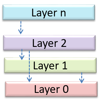
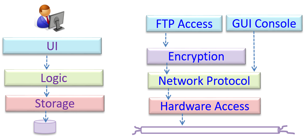
The n-tier architecture utilizes this principle. Each layer in the architecture has a well-defined functionality that has no functional overlap with each other.
Can identify n-tier architectural style
In the n-tier style, higher layers make use of services provided by lower layers. Lower layers are independent of higher layers. Other names: multi-layered, layered.
Operating systems and network communication software often use n-tier style.
This principle should lead to higher cohesion and lower coupling.
Can explain coupling
Coupling is a measure of the degree of dependence between components, classes, methods, etc. Low coupling indicates that a component is less dependent on other components. High coupling (aka tight coupling or strong coupling) is discouraged due to the following disadvantages:
- Maintenance is harder because a change in one module could cause changes in other modules coupled to it (i.e. a ripple effect).
- Integration is harder because multiple components coupled with each other have to be integrated at the same time.
- Testing and reuse of the module is harder due to its dependence on other modules.
In the example below, design A appears to have more coupling between the components than design B.
Exercises
Coupling levels of alternative designs
Discuss the coupling levels of alternative designs x and y.
Overall coupling levels in x and y seem to be similar (neither has more dependencies than the other). (Note that the number of dependency links is not a definitive measure of the level of coupling. Some links may be stronger than the others.). However, in x, A is highly-coupled to the rest of the system while B, C, D, and E are standalone (do not depend on anything else). In y, no component is as highly-coupled as A of x. However, only D and E are standalone.
Regressions and coupling
Explain the link (if any) between regressions and coupling.
When the system is highly-coupled, the risk of regressions is higher too e.g. when component A is modified, all components ‘coupled’ to component A risk ‘unintended behavioral changes’.
Coupling and testability
Discuss the relationship between coupling and a measure of how easily a given component can be testedtestability.
Coupling decreases testability because if the Software Under TestSUT is coupled to many other components, it becomes difficult to test the SUT in isolation of its dependencies.
Statements about coupling
Choose the correct statements.
- a. As coupling increases, testability decreases.
- b. As coupling increases, the risk of regression increases.
- c. As coupling increases, the value of automated regression testing increases.
- d. As coupling increases, integration becomes easier as everything is connected together.
- e. As coupling increases, maintainability decreases.
(a)(b)(c)(d)(e)
Explanation: High coupling means either more components are required to be integrated at once in a big-bang fashion (increasing the risk of things going wrong) or more drivers and stubs are required when integrating incrementally.
Can explain cohesion
Cohesion is a measure of how strongly-related and focused the various responsibilities of a component are. A highly-cohesive component keeps related functionalities together while keeping out all other unrelated things.
Higher cohesion is better. Disadvantages of low cohesion (aka weak cohesion):
- Lowers the understandability of modules as it is difficult to express module functionalities at a higher level.
- Lowers maintainability because a module can be modified due to unrelated causes (reason: the module contains code unrelated to each other) or many modules may need to be modified to achieve a small change in behavior (reason: because the code related to that change is not localized to a single module).
- Lowers reusability of modules because they do not represent logical units of functionality.
Exercises
Correct statements about SoC
“Only the GUI class should interact with the user. The GUI class should only concern itself with user interactions”. This statement follows from,
- a. A software design should promote separation of concerns in a design.
- b. A software design should increase cohesion of its components.
- c. A software design should follow single responsibility principle.
(a)(b)(c)
Explanation: By making ‘user interaction’ the GUI class’s sole responsibility, we increase its cohesion. This is also in line with the separation of concerns (i.e., we separated the concern of user interaction) and the single responsibility principle (the GUI class has only one responsibility).
Principles → Single responsibility principle
Can explain single responsibility principle
Single responsibility principle (SRP): A class should have one, and only one, reason to change. -- Robert C. Martin
If a class has only one responsibility, it needs to change only when there is a change to that responsibility.
Consider a TextUi class that does parsing of the user commands as well as interacting with the user. That class needs to change when the formatting of the UI changes as well as when the syntax of the user command changes. Hence, such a class does not follow the SRP.
Gather together the things that change for the same reasons. Separate those things that change for different reasons. ―- Agile Software Development, Principles, Patterns, and Practices by Robert C. Martin
Resources
- An explanation of the SRP from www.oodesign.com
- Another explanation (more detailed) by Patkos Csaba
- A book chapter on SRP written by the father of the principle itself, Robert C Martin
Guidance for the item(s) below:
Coordinating a team project is not easy. Given below are some very basic tools and techniques that are often used in planning, scheduling, and tracking projects.
Project Management → Project Planning → Milestones
Can explain milestones
A milestone is the end of a stage which indicates significant progress. You should take into account dependencies and priorities when deciding on the features to be delivered at a certain milestone.
Each intermediate product release is a milestone.
In some projects, it is not practical to have a very detailed plan for the whole project due to the uncertainty and unavailability of required information. In such cases, you can use a high-level plan for the whole project and a detailed plan for the next few milestones.
Milestones for the Minesweeper project, iteration 1
| Day | Milestones |
|---|---|
| Day 1 | Architecture skeleton completed |
| Day 3 | ‘new game’ feature implemented |
| Day 4 | ‘new game’ feature tested |
Project Management → Project Planning → Buffers
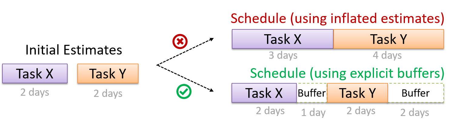
Can explain buffers
A buffer is time set aside to absorb any unforeseen delays. It is very important to include buffers in a software project schedule because effort/time estimations for software development are notoriously hard. However, do not inflate task estimates to create hidden buffers; have explicit buffers instead. Reason: With explicit buffers, it is easier to detect incorrect effort estimates which can serve as feedback to improve future effort estimates.
Project Management → Project Planning → Issue trackers
Can explain issue trackers
Keeping track of project tasks (who is doing what, which tasks are ongoing, which tasks are done etc.) is an essential part of project management. In small projects, it may be possible to keep track of tasks using simple tools such as online spreadsheets or general-purpose/light-weight task tracking tools such as Trello. Bigger projects need more sophisticated task tracking tools.
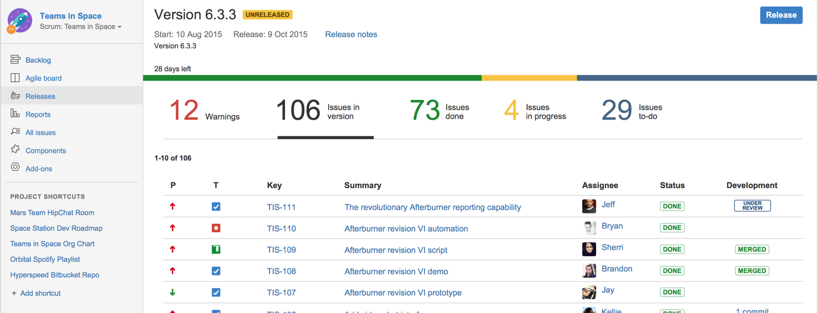
Issue trackers (sometimes called bug trackers) are commonly used to track task assignment and progress. Most online project management software such as GitHub, SourceForge, and BitBucket come with an integrated issue tracker.
A screenshot from the Jira Issue tracker software (Jira is part of the BitBucket project management tool suite):
Project Management → Project Planning → Work breakdown structure
Can explain work breakdown structures
A Work Breakdown Structure (WBS) depicts information about tasks and their details in terms of subtasks. When managing projects, it is useful to divide the total work into smaller, well-defined units. Relatively complex tasks can be further split into subtasks. In complex projects, a WBS can also include prerequisite tasks and effort estimates for each task.
The high level tasks for a single iteration of a small project could look like the following:
| Task ID | Task | Estimated Effort | Prerequisite Task |
|---|---|---|---|
| A | Analysis | 1 man day | - |
| B | Design | 2 man day | A |
| C | Implementation | 4.5 man day | B |
| D | Testing | 1 man day | C |
| E | Planning for next version | 1 man day | D |
The effort is traditionally measured in man hour/day/month i.e. work that can be done by one person in one hour/day/month. The Task ID is a label for easy reference to a task. Simple labeling is suitable for a small project, while a more informative labeling system can be adopted for bigger projects.
An example WBS for a game development project.
| Task ID | Task | Estimated Effort | Prerequisite Task |
|---|---|---|---|
| A | High level design | 1 man day | - |
| B |
Detail design
|
2 man day
|
A |
| C |
Implementation
|
4.5 man day
|
|
| D | System Testing | 1 man day | C |
| E | Planning for next version | 1 man day | D |
All tasks should be well-defined. In particular, it should be clear as to when the task will be considered done.
Some examples of ill-defined tasks and their better-defined counterparts:
| Bad | Better |
|---|---|
| more coding | implement component X |
| do research on UI testing | find a suitable tool for testing the UI |
Exercises
Which one is not a well-defined task?
Which one these project tasks is not well-defined?
(c)
Explanation: ‘More testing’ is not well-defined. How much is ‘more’? ‘Test the delete functionality’ is a better-defined task.
Project Management → Project Planning → Gantt charts
Can explain Gantt charts
A Gantt chart is a 2-D bar-chart, drawn as time vs tasks (represented by horizontal bars).
A sample Gantt chart:
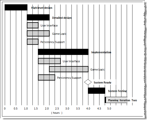
In a Gantt chart, a solid bar represents the main task, which is generally composed of a number of subtasks, shown as grey bars. The diamond shape indicates an important deadline/deliverable/milestone.
Project Management → Project Planning → PERT charts
Can explain PERT charts
A PERT (Program Evaluation Review Technique) chart uses a graphical technique to show the order/sequence of tasks. It is based on the simple idea of drawing a directed graph in which:
- Nodes or vertices capture the effort estimations of tasks, and
- Arrows depict the precedence between tasks
An example PERT chart for a simple software project
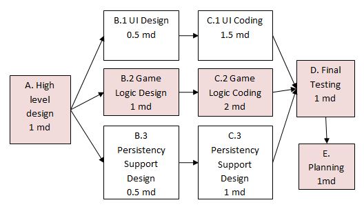
md = man days
A PERT chart can help determine the following important information:
- The order of tasks. In the example above,
Final Testingcannot begin until all coding of individual subsystems have been completed. - Which tasks can be done concurrently. In the example above, the various subsystem designs can start independently once the
High level designis completed. - The shortest possible completion time. In the example above, there is a path (indicated by the shaded boxes) from start to end that determines the shortest possible completion time.
- The Critical Path. In the example above, the shortest possible path is also the critical path.
Critical path is the path in which any delay can directly affect the project duration. It is important to ensure tasks on the critical path are completed on time.
Project Management → Teamwork → Team structures
Can explain common team structures
Given below are three commonly used team structures in software development. Irrespective of the team structure, it is a good practice to assign roles and responsibilities to different team members so that someone is clearly in charge of each aspect of the project. In comparison, the ‘everybody is responsible for everything’ approach can result in more chaos and hence slower progress.
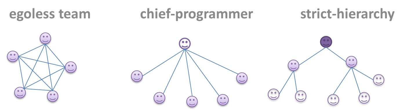
Egoless team
In this structure, every team member is equal in terms of responsibility and accountability. When any decision is required, consensus must be reached. This team structure is also known as a democratic team structure. This team structure usually finds a good solution to a relatively hard problem as all team members contribute ideas.
However, the democratic nature of the team structure bears a higher risk of falling apart due to the absence of an authority figure to manage the team and resolve conflicts.
Chief programmer team
Frederick Brooks proposed that software engineers learn from the medical surgical team in an operating room. In such a team, there is always a chief surgeon, assisted by experts in other areas. Similarly, in a chief programmer team structure, there is a single authoritative figure, the chief programmer. Major decisions, e.g. system architecture, are made solely by him/her and obeyed by all other team members. The chief programmer directs and coordinates the effort of other team members. When necessary, the chief will be assisted by domain specialists e.g. business specialists, database experts, network technology experts, etc. This allows individual group members to concentrate solely on the areas in which they have sound knowledge and expertise.
The success of such a team structure relies heavily on the chief programmer. Not only must he/she be a superb technical hand, he/she also needs good managerial skills. Under a suitably qualified leader, such a team structure is known to produce successful work.
Strict hierarchy team
At the opposite extreme of an egoless team, a strict hierarchy team has a strictly defined organization among the team members, reminiscent of the military or a bureaucratic government. Each team member only works on his/her assigned tasks and reports to a single “boss”.
In a large, resource-intensive, complex project, this could be a good team structure to reduce communication overhead.
Exercises
Which team structure is the most suitable for a school project?
Which team structure is the most suitable for a school project?
(a)
Explanation: Given that students are all peers and beginners, the egoless team structure seems most suitable for a school project. However, since school projects are low-stakes, short-lived, and small, even the other two team structures can be used for them.
Guidance for the item(s) below:
Testing is the first thing that comes to mind when you hear 'Quality Assurance' but there are other QA techniques that can complement testing. Let's first take a step back and take a look at QA in general, followed by a look at some other QA techniques.
Quality Assurance → Quality Assurance → Introduction → What
Can explain software quality assurance
Software Quality Assurance (QA) is the process of ensuring that the software being built has the required levels of quality.
While testing is the most common activity used in QA, there are other complementary techniques such as static analysis, code reviews, and formal verification.
Quality Assurance → Quality Assurance → Introduction → Validation versus verification
Can explain validation and verification
Quality Assurance = Validation + Verification
QA involves checking two aspects:
- Validation: are you building the right system i.e., are the requirements correct?
- Verification: are you building the system right i.e., are the requirements implemented correctly?
Whether something belongs under validation or verification is not that important. What is more important is that both are done, instead of limiting to only verification (i.e., remember that the requirements can be wrong too).
Exercises
Statements about validation and verification
Choose the correct statements about validation and verification.
- a. Validation: Are we building the right product?, Verification: Are we building the product right?
- b. It is very important to clearly distinguish between validation and verification.
- c. The important thing about validation and verification is to remember to pay adequate attention to both.
- d. Developer-testing is more about verification than validation.
- e. QA covers both validation and verification.
- f. A system crash is more likely to be a verification failure than a validation failure.
(a)(b)(c)(d)(e)(f)
Explanation:
Whether something belongs under validation or verification is not that important. What is more important is that we do both.
Developer testing is more about finding bugs in the code, rather than bugs in the requirements.
In QA, system testing is more about verification (does the system follow the specification?) and acceptance testing is more about validation (does the system solve the user’s problem?).
A system crash is more likely to be a bug in the code, not in the requirements.
Quality Assurance → Quality Assurance → Code Reviews → What
Can explain code reviews
Code review is the systematic examination of code with the intention of finding where the code can be improved.
Reviews can be done in various forms. Some examples below:
-
Pull Request reviews
- Project Management Platforms such as GitHub and BitBucket allow the new code to be proposed as Pull Requests and provide the ability for others to review the code in the PR.
-
In pair programming
- As pair programming involves two programmers working on the same code at the same time, there is an implicit review of the code by the other member of the pair.
Pair programming:
Pair programming is an agile software development technique in which two programmers work together at one workstation. One, the driver, writes code while the other, the observer or navigator, reviews each line of code as it is typed in. The two programmers switch roles frequently. [source: Wikipedia]

A good introduction to pair programming:
-
Formal inspections
-
Inspections involve a group of people systematically examining project artifacts to discover defects. Members of the inspection team play various roles during the process, such as:
- the author - the creator of the artifact
- the moderator - the planner and executor of the inspection meeting
- the secretary - the recorder of the findings of the inspection
- the inspector/reviewer - the one who inspects/reviews the artifact
-
Advantages of code review over testing:
- It can detect functionality defects as well as other problems such as coding standard violations.
- It can verify non-code artifacts and incomplete code.
- It does not require test drivers or stubs.
Disadvantages:
- It is a manual process and therefore, error prone.
Resources
- 10 tips for reviewing code you don’t like - a blog post by David Lloyd (a Red Hat developer).
Quality Assurance → Quality Assurance → Static Analysis → What
Can explain static analysis
Static analysis: Static analysis is the analysis of code without actually executing the code.
Static analysis of code can find useful information such as unused variables, unhandled exceptions, style errors, and statistics. Most modern IDEs come with some inbuilt static analysis capabilities. For example, an IDE can highlight unused variables as you type the code into the editor.
The term static in static analysis refers to the fact that the code is analyzed without executing the code. In contrast, dynamic analysis requires the code to be executed to gather additional information about the code e.g., performance characteristics.
Higher-end static analysis tools (static analyzers) can perform more complex analysis such as locating potential bugs, memory leaks, inefficient code structures, etc.
Some example static analyzers for Java: CheckStyle, PMD, FindBugs
Linters are a subset of static analyzers that specifically aim to locate areas where the code can be made 'cleaner'.
Quality Assurance → Quality Assurance → Formal Verification → What
Can explain formal verification
Formal verification uses mathematical techniques to prove the correctness of a program.
An introduction to Formal Methods
by Eric Hehner
Advantages:
- Formal verification can be used to prove the absence of errors. In contrast, testing can only prove the presence of errors, not their absence.
Disadvantages:
- It only proves the compliance with the specification, but not the actual utility of the software.
- It requires highly specialized notations and knowledge which makes it an expensive technique to administer. Therefore, formal verifications are more commonly used in safety-critical software such as flight control systems.
Exercises
Absence of errors
Testing cannot prove the absence of errors. It can only prove the presence of errors. However, formal methods can prove the absence of errors.
True
Explanation: While using formal methods is more expensive than testing, it can indeed prove the correctness of a piece of software conclusively, in certain contexts. Getting such proof via testing requires exhaustive testing, which is not practical to do in most cases.
Guidance for the item(s) below:
One of the primary goals of a software engineer is to avoid bugs. You certainly don't want to be the person responsible for causing a major bug that caused heavy damages to some party. That's why we need to focus heavily on testing -- one of the main defences against bugs.
The next few sections cover some intermediate level testing topics that you are very likely to encounter in software engineering.
Quality Assurance → Testing → Introduction → Testability
Can explain testability
Testability is an indication of how easy it is to test an SUT. As testability depends a lot on the design and implementation, you should try to increase the testability when you design and implement software. The higher the testability, the easier it is to achieve better quality software.
C++ to Java → JUnit → JUnit: Intermediate
Can use intermediate features of JUnit
Skim through the JUnit 5 User Guide to see what advanced techniques are available. If applicable, feel free to adopt them.
Quality Assurance → Testing → Test-Driven Development → What
Can explain TDD
Test-Driven Development(TDD) advocates writing the tests before writing the SUT, while evolving functionality and tests in small increments. In TDD you first define the precise behavior of the SUT using test cases, and then write the SUT to match the specified behavior. While TDD has its fair share of detractors, there are many who consider it a good way to reduce defects. One big advantage of TDD is that it guarantees the code is testable.
Exercises
When do we write tests in TDD?
A) In TDD, we write all the test cases before we start writing functional code.
B) Testing tools such as JUnit require us to follow TDD.
A) False
Explanation: No, not all. We proceed in small steps, writing tests and functional code in tandem, but writing the test before we write the corresponding functional code.
B) False
Explanation: They can be used for TDD, but they can be used without TDD too.
Follow up notes for the item(s) above:
You are welcome to, but not required to, follow the TDD approach in your project.